

GUIDE TO INSTALLATION
Guide To Installation: AM-BOSS Access-Boss
Guide To Installation: AM-BOSS All-Metal Access Ladder
Guide To Installation: AM-BOSS Big-Boss
Guide To Installation: AM-BOSS Into Suspended Ceilings
Guide To Installation: AM-BOSS Fire Rated Access Ladder
FOR TYPES, ACCESS-BOSS™ - Download PDF Version
AM-BOSS Access Ladders are CodeMark Certified
! IMPORTANT ! READ ALL OF THIS TEXT, TO PREVENT INJURY AND AVOID MISTAKES
GUIDE TO INSTALLATION FOR TYPES: ‘ACCESS-BOSS™’
STEP ONE: To get started, find the right location. Easy access top and bottom is essential. Make sure there is enough room to unfold the ladder (refer to Diagram / Table overleaf – Maximum Clearance at 60°).
IMPORTANT NOTE: CUT-OUT NOT TO BE WIDER AS SHOWN (570mm)
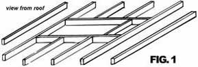
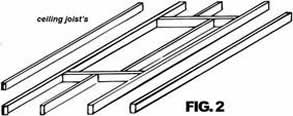
STEP TWO: What you need to make the opening – Timber Joist (Fig. 1 and Fig. 2): Timber, MPG10, 90x45mm pine or hardwood, about four (4) metres will be enough, pick a straight piece with minimal knots, and about 2 doz. 90mm long nails.
What you need to make the opening – Trusses (Fig. 3):
Trusses at 600mm centres should give you a clear distance of 565mm between. Insert a trimmer at length of 568mm (if Trusses are spaced at less than 565mm in between, smaller hatches can be manufactured at extra cost). DO NOT CUT TRUSSES without Building Surveyor approval.
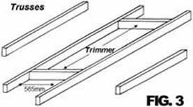
Web of trusses NOT SHOWN for clarity of sketch.
To mark out the opening on the ceiling: Either (from below) hammer nails through the plaster or (from above) measure from the top plates of the walls, which are usually visible. DO NOT STAND on the plaster ceiling or on timber joists that you had to cut, before it is nailed back to secure timber. A short plank is handy. It is best to do the timber work first, from above. Double check the cut out size and measure diagonally for square, if correct, cut out the plaster. You are now ready to install the unit.
Once the opening in the ceiling has been made, installation is a breeze.
! IMPORTANT ! READ ALL OF THIS TEXT, TO PREVENT INJURY AND AVOID MISTAKES
STEP THREE: Installation of the pull-down access ladder, into the readymade opening: Fit eyebolt to panel. Make sure opening end of hatch is where it should open and have someone assist you for 5 minutes to push the fully assembled access ladder into the ceiling, ensuring the architrave is hard against the plaster. The unit is now in the right position and should not fall back out - fitted Fixing Clips will take care of that. Gently open the hatch panel with the hook & pole supplied, by placing the hook through the eyebolt, (at this time, with one hand keeping pressure against the architrave at the opening end) immediately screw one screw (8 x Type 17 Hex screws 12-11 x 65mm supplied, or use similar) into each pre-drilled hole on either side at opening end through frame to timber to secure. Unfold the ladder. DO NOT WALK ON THE LADDER AT THIS TIME. Now screw remaining six (2x3) screws into the remaining pre-drilled holes. You may have to loosen or tighten the eight (8) fixing screws on one side or the other to adjust the gap evenly on both sides between the architrave and the panel. Now all you have to do is adjust the ladder (two screws with lock nuts – refer Adjustment sticker inside frame), so that feet are on the floor and hinges are closed ie butted against each other, finished.
If you cannot get someone to help you: Remove the ladder assembly only from the panel, (4 or 6 nuts depending on model) to lighten the load. Make sure the hatch panel opens at the right end. With a rope, pull the hatch from above into the ceiling. Make sure the hatch-architrave is hard against the ceiling. Fix the frame by screwing the eight screws (supplied) through frame to timber to secure. From below open the hatch, ! ATTENTION ! Be careful - without the weight of the ladder it is possible for the panel to fly up. Keep the ladder assembly nearby and fit it back on the panel with the 4 or 6 nuts. Do not over tighten the nuts. You may have to loosen or tighten the eight (8) fixing screws on one side or the other to adjust the gap evenly on both sides between the architrave and the panel. Now all you have to do is adjust the ladder (two screws with lock nuts – refer Adjustment sticker inside frame), so that feet are on the floor and hinges are closed ie butted against each other, finished.
You are now ready to enjoy your new access system.
! IMPORTANT ! READ ALL OF THIS TEXT, TO PREVENT INJURY AND AVOID MISTAKES
OPERATING AND MAINTANANCE PROCEDURE
ON AM-BOSS ACCESS LADDERS
Am-boss Access Ladders work on a reliable counter balance spring system.
OPENING
Engage hook on pole (supplied) into small eyelet on opening end of ceiling access panel. Gently pull door open till it comes to rest against the stops on the adjusting mechanism. No need to unhook the pole from the panel. With both hands unfold and extend the ladder to the floor.
CLOSING
With both hands lift up bottom section of ladder and fold back up on top of each other. With the use of the pole gently first push then ease panel back up till it is fully closed. The spring counter balance system will keep the panel shut.
MAINTENANCE
All moving parts are factory pre-lubricated and lubrication should not be required for some time. However should operation of the unit be in excess of 3 to 5 times a day, all moving parts are to be lubricated once every two months. Most important is the lubrication of the Pivot Point of the linkage-arms joined to the side plate with the adjusting system. This part does most of the work.
INSPECTION OF THE WHOLE SYSTEM SHALL BE CARRIED OUT ONE A YEAR AND ACTION TAKEN
Cut out NOT TO BE WIDER as shown (570mm)
Ceiling cut-out sizes: Model No's 2153 to 2680 - 1220mm x 570mm
Ceiling cut-out sizes: Model No's 2830 to 3840* - 1520mm x 570mm
* Ceiling cut-out for Model 3840 for ceiling heights from 3945mm to 3995mm - 1620mm x 570mm
|
MODEL |
CEILING HEIGHT |
UNFOLD (A) |
REST POINT (B) |
|---|---|---|---|
|
2153 |
2150mm-2300mm |
1595mm |
1465mm |
|
2345 |
2300mm-2450mm |
1670mm |
1525mm |
|
2460 |
2450mm-2600mm |
1720mm |
1555mm |
|
2680 |
2600mm-2800mm |
1830mm |
1700mm |
|
2830 |
2800mm-3000mm |
1950mm |
1790mm |
|
3020 |
3000mm-3200mm |
2050mm |
1855mm |
|
3240 |
3200mm-3400mm |
2145mm |
1970mm |
|
3460 |
3400mm-3600mm |
2210mm |
2005mm |
|
3680 |
3600mm-3800mm |
Manufactured on-grade at 68° approx., |
|
|
3840 |
3800mm-3995mm |
||
|
From 4000mm Measurements and Cut-out To Be Advised |
|||
|
NO ASSEMBLY, NO CUTTING, NO MISTAKES. |
|||
